

Choosing the right equipment for the PHASED ARRAY test is always one of the important stages of the test and it is selected according to the manufacturing standard and technical details of the equipment to be tested, and in this guide, the suggestions that are the result of using the standards and experiences of the experts can be seen:
1 . Equipment:
The main equipment of Phased Array test is as follows
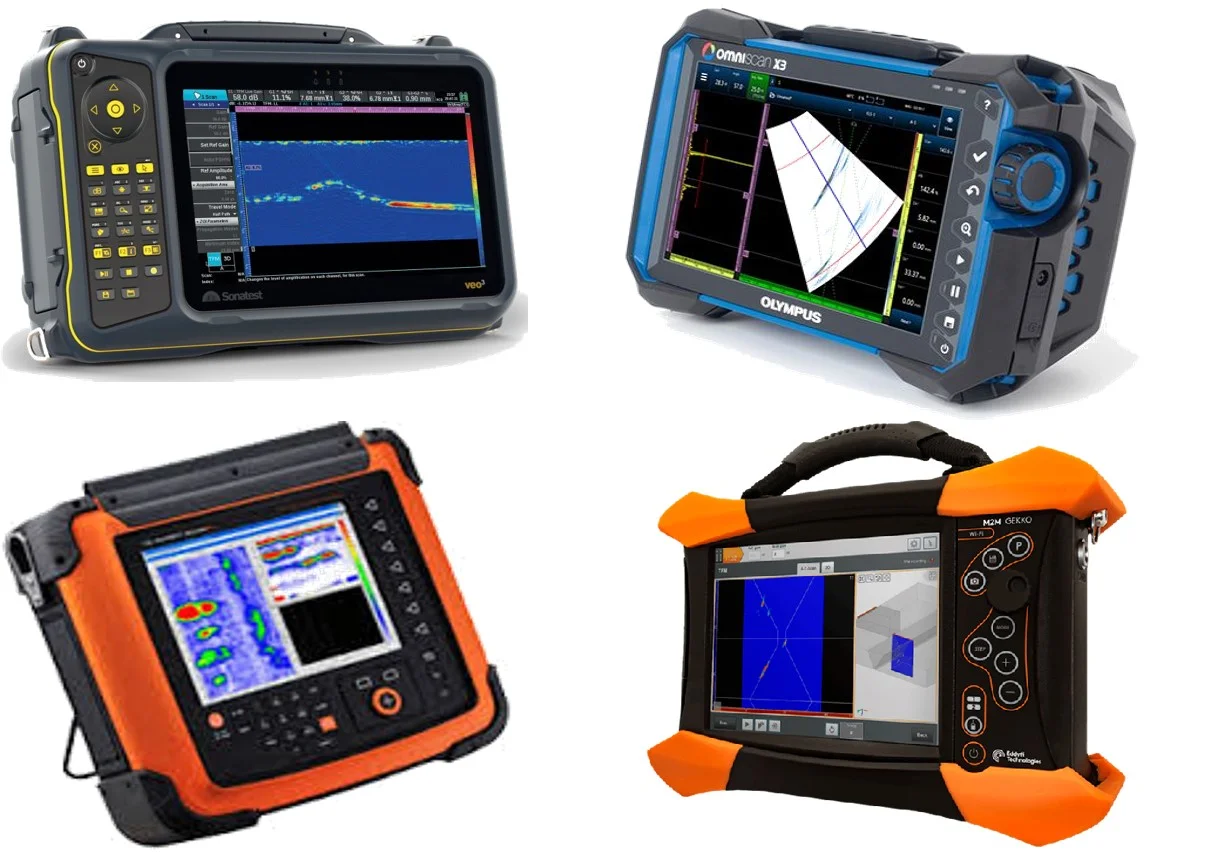
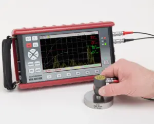
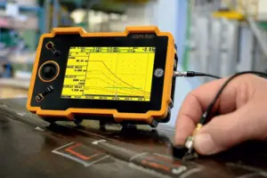
- Phased Array device
- Phased Array Probe
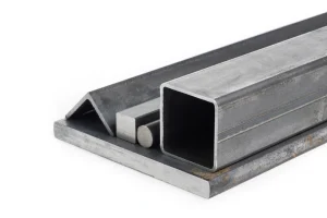
- Sensitivity calibration blocks
- Distance calibration blocks
- scanner
2 . Application:
In this guide, the Phased Array test is reviewed for the scope of use in the following cases
- Testing of pressure vessel welds designed according to ASME Sec VIII standard
- Testing of welds of storage tanks designed according to API 650 and API 620 standards
- Welding test of pressure pipes designed according to ASME B31.1 and ASME B31.3 standards
- Welding test of pipelines designed according to API 1104 standard
- Find service-induced defects to check remaining life in accordance with API 579
-
Continue reading (Ultrasonic test in welding qualification verification)
-
Continue reading (POD on various NDT methods)
-
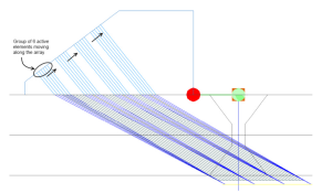
Continue reading (Types of Sound Propagation in Phased Array)
3. Equipment selection
3.1 Choosing an advanced ultrasonic device:
domain of usage |
thickness |
The number of two-channel pulses |
Capabilities |
welding test
|
up to 55 mm |
At least 16 pulsers and 64 channels |
Perform Phased Array and ToFD simultaneouslyThe possibility of connecting two PAUT probes at the same timeHas at least one pair of ToFD channelsPreparation of the output file that can be analyzed on the softwareAbility to connect encoderAbility to perform 4 scanning groups at the same time |
55 to 130 mm |
At least 32 pulsers and 64 channels |
||
From 130 mm to more |
At least 32 pulsers and 128 channels |
||
Finding defects in equipment bodies and pipes caused by service to check the remaining life according to API 579 standard (other than welding) |
up to 55 mm |
At least 8 pulsers and 16 channels |
Perform 2 Phased Array scans at the same timeAbility to save the image of the defect locationThe ability to connect the encoder when preparing the corrosion map |
55 to 100 mm |
At least 16 pulsers and 64 channels |
||
From 100 mm to more |
At least 32 pulsers and 64 channels |
3.2 Phased Array Probe Selection: (Also read: Probe Position Calculations)
thickness |
Frequency |
The number of elements |
pitch |
Thickness up to less than 6 mm |
10 MHz |
At least up to 16 elements |
0.3 to 0.6 mm |
Thickness 6 to 10 mm |
7.5 to 10 MHz |
At least up to 16 elements |
0.3 to 0.6 mm |
Thickness 10 to 16 mm |
5 to 7.5 MHz |
At least up to 16 elements |
0.3 to 0.6 mm |
Thickness 16 to 55 mm |
5 MHz |
At least up to 16 elements |
0.5 to 0.8 mm |
Thickness 55 to 85 mm |
2.25 to 5 MHz |
At least up to 32 elements |
0.6 to 0.8 mm |
Thickness 85 to 100 mm |
2.25 to 5 MHz |
At least up to 32 elements |
0.8 to 1 mm |
Thickness from 100 mm to higher |
2.25 MHz |
At least up to 32 elements |
0.8 to 1.2 mm |
3.3 Selection of Wedge Phased Array:
domain of usage |
shoe material |
Sound exit angle |
Description |
Phased Array welding test for all application domains of Clause 2 |
Rexolite |
45 degrees of longitude45 degree latitude55 degrees latitude60 degrees of longitude60 degrees latitude |
In the welding test of pipes up to less than 20 inches, the shoe should have an arc proportional to the diameter of the pipe |
ToFD welding test for all domains of application Paragraph 2 |
Rexolite |
45, 60, 65 and 70 degrees |
The material of the shoe body is not a fundamental variable and the material of the center of the shoe must be observed |
Finding defects in equipment bodies and pipes caused by service to check remaining life in accordance with API 579 standard (other than welding) |
PrespexorRexolite |
zero degree |
The maximum thickness that can be tested is about twice the thickness of the shoeRexolite shoe should be used for thickness above 60 |
3.4 TCG/DAC sensitivity block selection:
domain of usage |
Weld thickness |
Block thickness |
SDH diameter |
Description |
Pressure vessel welding testDesigned according to the standardASME Sec VIII |
up to 25 mm |
± 25 %Weld thickness |
up to 2.5 mm parallel to the surface |
The material of the block should be the same as the welding material.The conditions of the block surface should be as similar as possible to the test pieceIf there is a difference in the manufacturing process of the material of the block and the piece, the sound transmission coefficient should be calculatedIt has 3 SDH in the depths of ¼, ½, ¾ thickness of the block |
25 to 50 mm |
± 25 %Weld thickness |
up to 3 mm parallel to the surface |
||
50 to 100 mm |
± 25 %Weld thickness |
up to 5 mm parallel to the surface |
||
From 100 mm to more |
± 25 %Weld thickness |
For every 50 mm increase in thickness up to 1.5 mm is added to the SDH size of the previous step. |
To use the above blocks in tubular parts, if the surface of the block has an arc corresponding to the pipe under test, the use of the same block and reflectors is allowed.
3.5 Selecting the scanner block:
A piece of block of real material to be tested under the following conditions should be prepared by the employer and provided to the operators for daily checking of the system performance.
- In the sheet welding test, this piece should be at least 50 cm long and with a thickness of ±25%.
- In the pipe welding test of this part, at least half of the circumference of the circle, the thickness of the test weld should be ±25% and its diameter should be in the range of 0.9 to 1.5 times that of the main pipe under test.
- The connection scheme should be similar to the part under test.
- Defects are artificial or real, and the number, location and size of defects should be determined with the advice of PAUT level 3 expert.
- The scanner block can be used to confirm the qualification of instructions and scan plan if approved by the level 3 expert
- If the exact size and type of defects are known, the above block can be used as a block for preparing sizing instructions.
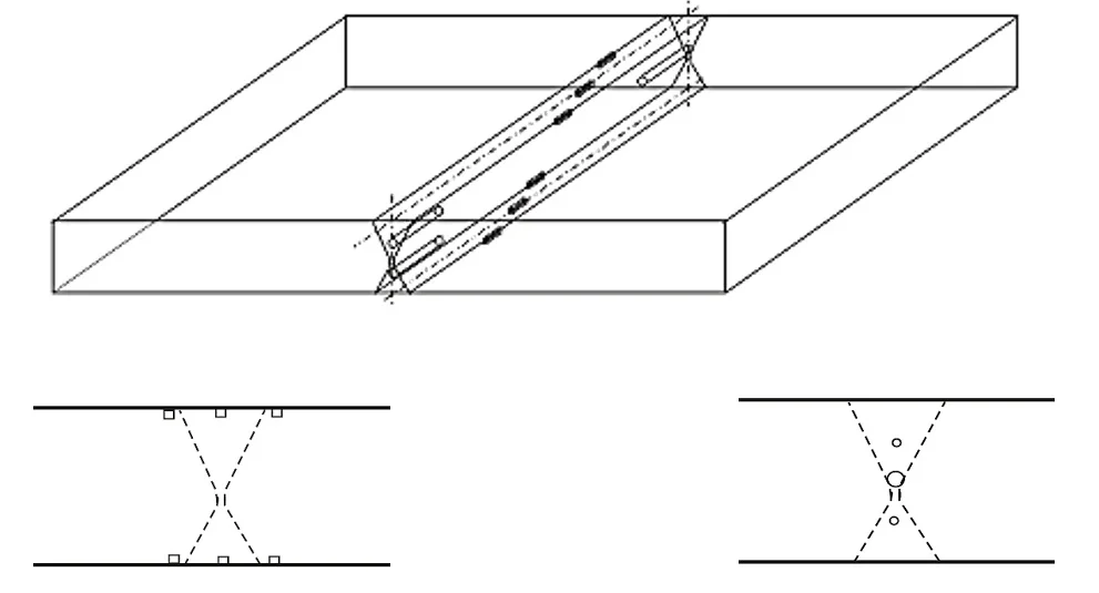
The recommended plan for preparing blocks with artificial defects is as follows:
3.6 انتخاب اسکنر :
domain of usage |
Scanner required |
Capabilities |
Testing of pressure vessel welds designed according to ASME Sec VIII standard |
Fully automatic scanner or semi-automatic scanner |
The possibility of installing at least two Phased Array probesAbility to install at least two ToFD probesThe possibility of installing and connecting the encoderIt has adhesive magnetic wheels or other mechanisms to connect to the tank |
Test of welds of storage tanks designed according to API 650 and API 620 standards |
Fully automatic scanner |
The possibility of installing at least two Phased Array probesAbility to install at least two ToFD probesThe possibility of installing and connecting the encoderIt has adhesive magnetic wheels or other mechanisms to connect to the tank |
Welding test of pressure pipes designed according to ASME B31.1 and ASME B31.3 standards |
Fully automatic scanner or semi-automatic scanner |
The possibility of installing up to two Phased Array probesAbility to install up to two ToFD probesThe possibility of installing and connecting the encoderIt has adhesive magnetic wheels or other mechanisms to connect to the tank |
Welding test of pipelines designed based onAPI 1104 standard |
Fully automatic scanner or semi-automatic scanner |
The possibility of installing up to two Phased Array probesAbility to install up to two ToFD probesThe possibility of installing and connecting the encoderIt has adhesive magnetic wheels or other mechanisms to connect to the tank |
Finding defects in equipment bodies and pipes caused by service to check remaining life in accordance with API 579 standard (other than welding) |
Fully automatic scanner or semi-automatic scanneror manual scanning |
The ability to connect and connect the encoder when preparing a corrosion map |